ROOF TRUSS DESIGN INFORMATION
Learn different truss components and how trusses are manufactured.
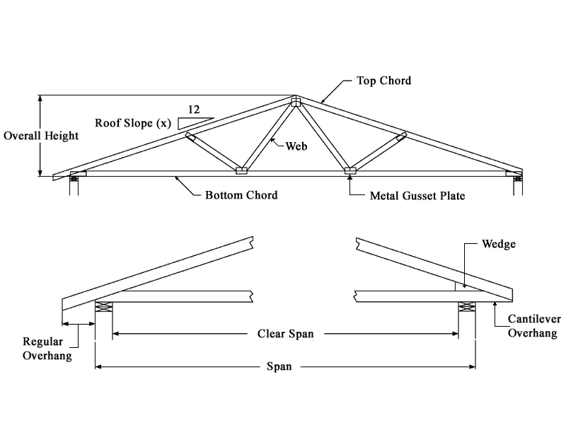
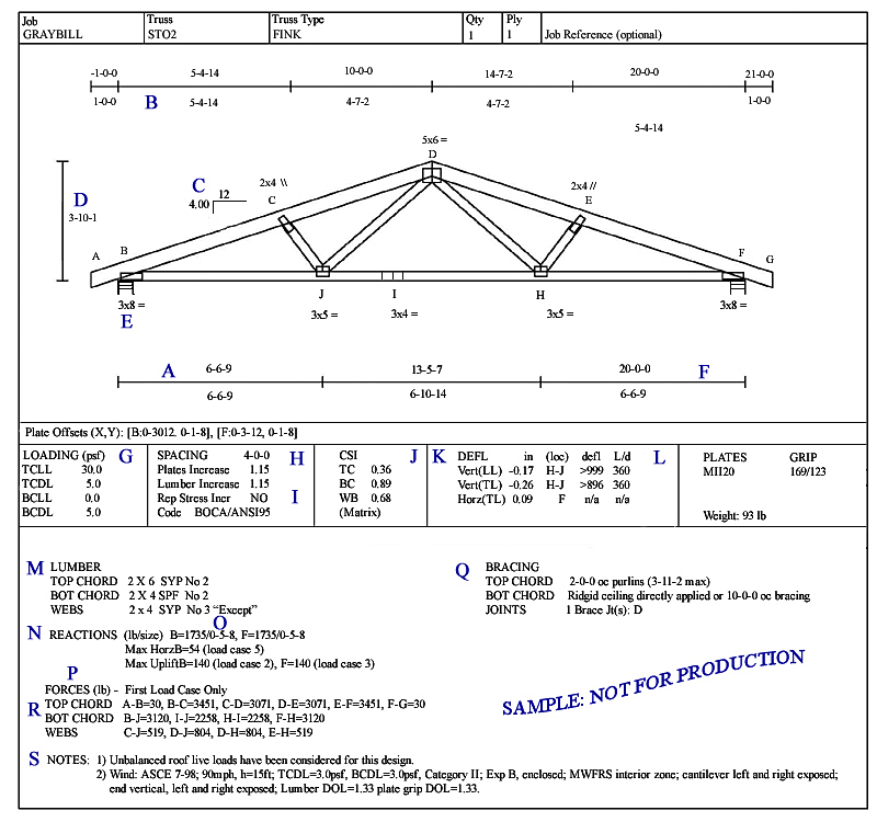
Shown is a sample of a typical detailed truss drawing provided by most of the truss manufacturing companies. This kind of drawing is done by an engineer who designs the truss according to local building codes. During initial truss design, everything must be taken into consideration. Web bracing and the size of top & bottom chords will depend on factors such as number of bearing points, truss span between bearing points, roof pitch, truss spacing, ground snow loads, live & dead loads and many other factors. Below, you will find definition of different truss components.
- A: Cumulative Dimensions
- B: Panel Length (feet-inches-sixteenths)
- C: Slope (roof pitch)
- D: Overall Height
- E: Bearing Locations
- F: Truss Span
- G: Design Loading (PSF)
- H: Spacing O.C. (feet-inches-sixteenths)
- I: Durations of Load for Plate & Lumber Design
- J: Top Chord, Bottom Chord and Web.
Maximum Combined Stress Indices.
- K: Deflections (inches) and Span to Deflection Ratio
- L: Allowable Deflection Ratio
- M: Lumber Requirements
- N: Reaction (pounds)
- O: Minimum Bearing Required (inches)
- P: Maximum Uplift and/or Horizontal Reaction if Applicable
- Q: Required Member Bracing
- R: Member Axial Forces For Load Case 1
- S: Notes
- T: